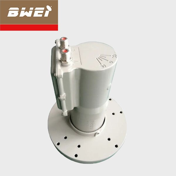
Single Feed Horn/Dual Feed Horn+filter+LNB
If you have any questions about product transactions and technical consultation, please contact us, we will reply you within one working day.
Single Feed Horn
| Frequency Range | 3.4-4.2GHz |
| Return Loss | >10dB |
| interface | BJ40 |
| Operating temperature | -40℃~+70℃ |
| stored temperature | -40℃~+80℃ |
| Relative humidity | 0%~95% |
| Pack size heavy | 17*20*10.5cm/ 343g |

Dual Feed Horn

| Frequency Range | 3.4-4.2GHz |
| Return Loss | >10dB |
| interface | BJ40 |
| Operating temperature | -40℃~+70℃ |
| stored temperature | -40℃~+80℃ |
| Relative humidity | 0%~95% |
| Pack size heavy | 17cm*20*10.5cm/565g |
Filter
The working frequency band of the 5G communication base station overlaps with the 3.4-4.2GHz satellite signal frequency band by nearly 300MHz. Microwave interference and pulse interference appear at the receiving end of the C-band satellite communication, which seriously affects the quality of satellite signal reception. Data packet loss is very serious, and even This will cause signal mosaic or interruption, which will have a great impact on the signal receiving work of radio and television, financial institutions, and meteorological agencies.
Therefore, the interference suppression satellite filter of the C-band satellite signal integrated receiving decoder is required, and its working bandwidth is 3625-4200MHz, 3700-4200MHz (satellite earth station C-band), which requires good in-band flatness and high out-of-band suppression efficiency.
If you want some products with special specifications, please contact us, we will reply you within one working day.


At present, the cavity waveguide bandpass filter is mainly used. Its working principle is to induce the vibrator of the corresponding frequency through electromagnetic waves, usually a level 5 vibrator, and the signal attenuation is slightly larger. The advantage is that the cavity waveguide is relatively long, which is effective for areas with strong interference signals. Very good anti-jamming effect.
| Passband Frequency | 3.9-4.2GHz |
| IL | ≤0.5dB |
| VSWR | ≤1.25 |
| Group Delay Variation | ≤8 ns Typ |
| Rejection | 3.3-3.7GHz; 4.4-6GHz |
| out-of-band suppression | 50 dB typ |
| Ports | Flange: CPR229G, CPR229F |
| Material | Alumminum |
LNB

| Input Fre. | 3.7-4.2GHz | FTA | Yes |
| L.O. Fre. | 5150MHz | HD | Yes |
| Output Fre. | 950-1450MHz | Type | Digital |
| Local vibration stability | ±1.5MHz | Noise coefficient | <17°K typ |
| Gain | >55dB typ | Gain flatness | ±1 dBm (max) |
| Input VSWR | 2.5:1 (max) | Output VSWR | 2.0:1 (max) |
| Output connection | F-female | Output impedance | 75Ω |
| Polarization isolation | 20dB (min) | mirror frequency suppression | 45 dB (min) |
| Phase noise | -75dB/Hz@10kHz (max) | ||
| Supply voltage | 11.5-14.0V (V) | ||
| 16.0-19.0V (H) | |||
| Operating temperature | -40 ℃ to +70 ℃ | ||
| Storage temperature | -40 ℃ to +80 ℃ | ||
| Relative humidity | 0%-95% | ||
| Package | 10*16.5*7.5cm/280g | ||